Interface formula
\[
\text{Return Loss (dB)} = 10 \times \log_{10}\!\Bigl(\bigl(\tfrac{n_1 - n_2}{n_1 + n_2}\bigr)^2\Bigr)
\]
where \(n_1\) is the reflectance of Cable A endface.
where \(n_2\) is the reflectance of Cable B endface.
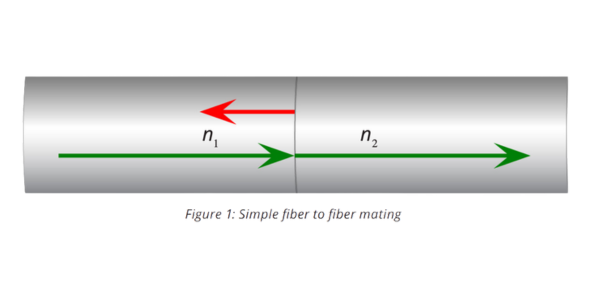
The term Optical Return Loss typically describes total return loss across a cable assembly or a link. The term Reflectance describes a single reflection in an optical assembly. Reflectance occurs at point discontinuities, for example connector interfaces, splice interfaces, etc. Typically, Return Loss is reported as a positive number and Reflectance is a negative number. The industry commonly uses the term Optical Return Loss when related to connectors and mated connections.
\[
\text{Return Loss (dB)} = 10 \times \log_{10}\!\Bigl(\bigl(\tfrac{n_1 - n_2}{n_1 + n_2}\bigr)^2\Bigr)
\]
where \(n_1\) is the reflectance of Cable A endface.
where \(n_2\) is the reflectance of Cable B endface.
Low return loss is critical in ensuring operability of fiber optic communication systems. As transmission rates increase and more complicated communication schemes are implemented, such as PAM4, any return loss becomes a strong concern. Return loss is the result of back reflections, and excessive back reflections can induce noise on the signal leading to increased data transmission errors. There are many sources of return loss in a fiber optic system.
Refractive index mismatches at the mating interface
Refractive index changes due to the polishing process
Refractive index changes due to fiber deformation from the connector spring force (Hertzian contact stress)

Differences in refractive indexes between the two mated fibers