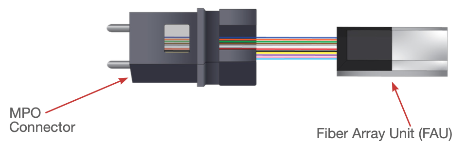
Cable assemblies featuring a Fiber Array Unit (FAU) are increasingly more common. These assemblies consist of a fiber array on one end and a standard fiber optic connector (such as MPO, LC, SC) on the other. This trend is driven by the necessity to direct fiber optic signals from a standardized connector within a conventional fiber optic network to a Photonic Integrated Circuit (PIC). The fiber array serves as a precise alignment tool, ensuring the accurate alignment of multiple fibers into the waveguides of the PIC or other compact optical devices. Typically, fibers are arranged at a consistent pitch and in a row, ensuring alignment with the internal structures of the system, whether it is a PIC or another optical system.
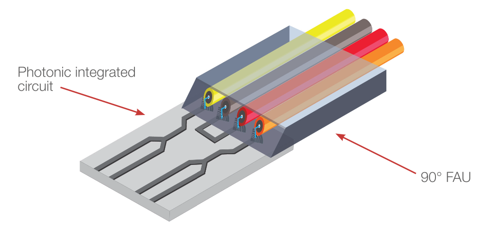
Testing short fiber array assemblies for insertion loss can pose challenges due to their non-standard nature. These FAU assemblies are often highly customized to suit the specific systems they will connect to. Some arrays are designed for butt coupling to edge-coupled waveguides, while others deflect light at close to 90 degrees to route the signals into an array of grating couplers.
Testing insertion loss on FAU assemblies may initially seem simple. However, due to the custom nature of FAU assemblies, special attention is necessary to guarantee accurate and repeatable measurements. To test insertion loss on these assemblies, a measurement system must include:
1. A stabilized light source
2. A repeatable multichannel optical switch for automation of port/channel testing
3. An optical power meter with uniform response across the working area
4. An optical power meter with a large enough aperture to accommodate the full width of the fiber array ports
5. A detector adapter that correctly routes light from the FAU into the detector and securely holds the cable assembly to prevent damage during the measurement process.
The multichannel BRM-100 meets all these requirements. Its optical source includes an internal power monitor, which effectively corrects power fluctuations caused by environmental shifts. This feature reduces the need for frequent re-referencing during the manufacturing process of many assemblies and ensures minimal drift during assembly measurements, even in the presence of environmental changes, which are quite common in non-climate-controlled production environments. The BRM-100’s internal optical switch allows for automated testing of multiple ports within an FAU assembly with high repeatability, ±0.005dB, yielding precise power switching across all fiber array ports.
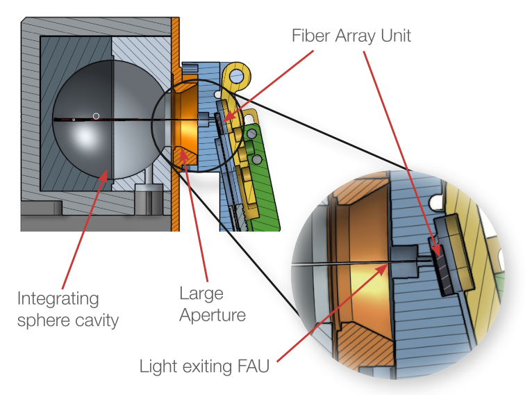
Additionally, its integrating sphere has an aperture of up to 11.3mm in diameter, capable of accommodating accurate power measurement of most typical FAUs. The large aperture and uniformity guarantees accurate power measurements across the entire row or rows of
fibers in the FAU.
Given the intricate and custom nature of many fiber arrays, careful attention to the OPM adapter is critical to ensure accurate light measurement from the FAU.
Custom adapters are often necessary, and Santec can design them based on provided mechanical dimensions to ensure proper fit and alignment of the fiber array within the sphere.
Testing FAUs designed to emit light at close to a 90-degree angle can lead to significant challenges, especially when connecting them to the OPM, which may require bending the assembly awkwardly within the workspace. It’s critical to make sure that the assembly isn’t twisted or bent significantly during testing to maintain measurement accuracy and prevent damage. Given the fragile nature of such assemblies, the OPM adapter should secure the FAU and ribbon fiber in place without damaging the assembly and or fraying the ribbon fiber.
To test insertion loss on the fiber array assembly one needs:
1. BRM with the proper channel count
2. Remote head integrating sphere
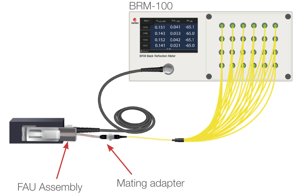
3. Fanout reference cord to mate to the cable assembly
4. Mating adapter to connect the reference cord to the fiber array assembly
5. Custom power meter adapter to accommodate FAU
Insertion Loss Measurement Process
The referencing process requires a fanout cord to be connected to BRM. This reference cord should be high quality and free from damage.
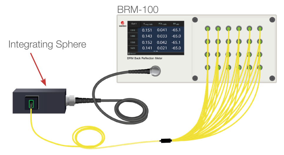
The reference cord’s connector is plugged into the OPM using the appropriate power meter adapter. The power level is recorded and stored on the meter as a reference for each channel and wavelength.
To measure the assembly, mount the FAU into the OPM adapter and secure it firmly. Ensure the assembly remains free of bends and twists to prevent potential damage. Connect the reference cord to the assembly using a mating adapter. Slide the OPM adapter, containing the FAU, over the OPM, and secure it in place. Once secured, the system can measure the insertion loss of the assembly. It will cycle through all channels, measure power, compare it against the reference power, and determine a pass or fail based on the cable assembly criteria.
Testing FAU assemblies can pose challenges and guaranteeing repeatable and accurate measurements can be difficult. However, by employing the Santec multichannel BRM-100 alongside a custom optical power meter adapter, one can achieve highly accurate and consistent measurements.
For more information on the BRM-100 and its capabilities, BRM-100 Product Page.