
Insertion Loss Testing Methods Explained

Introduction to Insertion Loss
Insertion loss is a critical parameter in optical and electrical systems because it directly influences the efficiency and performance of signal transmission. Whether in telecommunications, data centers, or photonics applications, insertion loss testing ensures systems operate with minimal signal degradation, maintaining reliability and accuracy.
What Is Insertion Loss?
Insertion loss refers to the reduction of signal power caused when a device or component is introduced into a transmission line. It is measured in decibels (dB) and is a key indicator of how much signal strength is lost during transmission. In simple terms, it quantifies the loss between the input power (Pin) and output power (Pout), calculated using the formula:
| IL (dB) = 10 × log10 (Pin / Pout) |
Suppose an optical signal with a power of 1 mW enters a fiber and exits at 0.5 mW. In that case, the insertion loss would be 3 dB. In optical systems, insertion loss can occur due to factors like fiber attenuation, misaligned connectors, splicing imperfections, and bends in the fiber.
Why Is Insertion Loss Testing Important?
Accurate insertion loss testing is vital for maintaining the integrity of communication systems. Excessive signal loss can cause transmission errors, reduced data rates, and decreased system efficiency. For industries like telecommunications, fiber insertion loss testing ensures networks meet performance standards, providing seamless data transfer over long distances.
Insertion loss testing is important for validating the quality of fiber optic components, like connectors, splices, and cables. For data centers and optical networks, precise testing helps ensure connections remain efficient, minimizing downtime and reducing maintenance costs.
Key Applications in Optical Systems
Insertion loss testing is applied in several critical areas:
● Telecommunications: Ensures fiber optic networks deliver high-speed, low-loss data transmission.
● Data Centers: Validates the performance of large-scale cabling systems for smooth, uninterrupted data flow.
● Photonics: Tests optical components used in research and development environments.
● Aerospace and Defense: Ensures robust, reliable signal performance in mission-critical optical systems."
Insertion Loss Testing Methods
Accurate measurement of insertion loss requires specialized testing techniques tailored to the system's complexity, distance, and operational goals. Two primary methods dominate insertion loss testing: direct testing using a light source and power meter and indirect testing using Optical Time Domain Reflectometry (OTDR). Both methods offer distinct advantages and are applied based on specific requirements.
Direct Testing with Light Source and Power Meter
Direct testing is one of the most straightforward and widely used methods for fiber optic insertion loss testing. It involves measuring the signal power before and after it passes through a device or fiber. The process is as follows:

1. A stabilized light source injects a known optical power level into the fiber at a specified wavelength.
2. A power meter measures the output power at the other end of the fiber.
3. The difference between the input power and the measured output power gives the insertion loss value.
For example, if the light source emits 0 dBm (1 mW) and the power meter detects -3 dBm (0.5 mW), the insertion loss is 3 dB.
Key advantages of direct testing include:
● Simplicity and ease of setup.
● High accuracy for short and medium-length fiber links.
● Cost-effective for routine testing and maintenance.
However, direct testing does not provide information on loss locations within the fiber. It measures total insertion loss but cannot pinpoint specific faults, splices, or bends."
OTDR (Optical Time Domain Reflectometry) Testing
OTDR testing is an indirect insertion loss testing method that provides a detailed analysis of the fiber optic link. Instead of measuring total signal loss, OTDR identifies and quantifies loss events along the fiber's length.

How OTDR works:
1. The OTDR sends short, high-intensity light pulses into the fiber.
2. As the light travels, a small portion is scattered back (Rayleigh scattering) or reflected at loss points (e.g., splices, connectors).
3. The OTDR measures the time and intensity of the returned signals, creating a graphical trace of the fiber's attenuation profile.
Benefits of OTDR testing include:
● Pinpointing the exact location of loss events, such as splices, bends, or faults.
● Assessing overall fiber health, including attenuation trends and signal degradation.
● Diagnosing issues in long-distance and complex optical systems.
For example, in telecommunications, OTDR testing helps identify splice losses across hundreds of kilometers of optical fiber, enabling engineers to locate and address specific problems without dismantling the entire network.
While OTDR testing provides comprehensive diagnostic data, it requires more sophisticated equipment and interpretation expertise. It is better suited for troubleshooting, installation verification, and long-distance fiber optic networks, whereas direct testing is ideal for routine measurements and simple link evaluations.
Comparing Insertion Loss Testing Techniques
Selecting the appropriate method for fiber optic insertion loss testing depends on the specific needs of the system being evaluated. Direct testing, which involves a light source and power meter, and OTDR (Optical Time Domain Reflectometry) testing are widely recognized techniques. Each approach offers unique advantages and is suited to different scenarios, making it crucial to understand their respective applications and limitations.
Direct vs. Indirect Testing
Direct Testing:
Direct testing, a widely used technique in fiber optic insertion loss testing, involves injecting a stabilized power level into the fiber using a light source and measuring the output with a power meter. This method offers simplicity, precision, and cost-effectiveness, making it ideal for short- to medium-length fiber links and routine system maintenance. However, its inability to pinpoint specific loss events, such as splices or connector issues, limits its application in diagnosing complex or long-distance networks.
Strengths:
● Simplicity: The process requires minimal setup and provides quick, reliable results.
● Versatility: Suitable for short- to medium-length fiber links as well as photonic devices where light travels across very short distances, making it an adaptable option for various applications.
● Accuracy: Direct testing delivers precise measurements for total insertion loss.
Weaknesses:
● Limited Diagnostics: Direct testing cannot pinpoint specific faults, such as connector loss or splicing issues.
● Inefficient for Long-Distance Networks: It cannot assess attenuation trends or locate faults in complex networks.
OTDR (Indirect Testing)
OTDR (Optical Time Domain Reflectometry) testing involves sending light pulses through the fiber and analyzing the backscatter and reflections to identify losses. This method generates a graphical trace that provides a detailed view of attenuation and specific loss events, such as splices, bends, or breaks.
While OTDR testing is highly effective for diagnosing long-distance or complex networks, offering precise fault location and overall fiber health assessment, it requires specialized equipment and expertise to interpret the results, making it less suitable for routine or short-link testing scenarios.
Strengths:
● Detailed Diagnostics: OTDR testing pinpoints the exact location and cause of signal loss, such as bends, breaks, or bad splices.
● Long-Distance Capability: It is ideal for fiber optic insertion loss testing in extended and complex networks.
● Comprehensive Data: OTDR provides a visual trace, offering insights into overall fiber health.
Weaknesses:
● Complexity: OTDR equipment requires more expertise for accurate setup and analysis.
● Higher Cost: OTDR devices are more expensive than basic insertion loss testers.
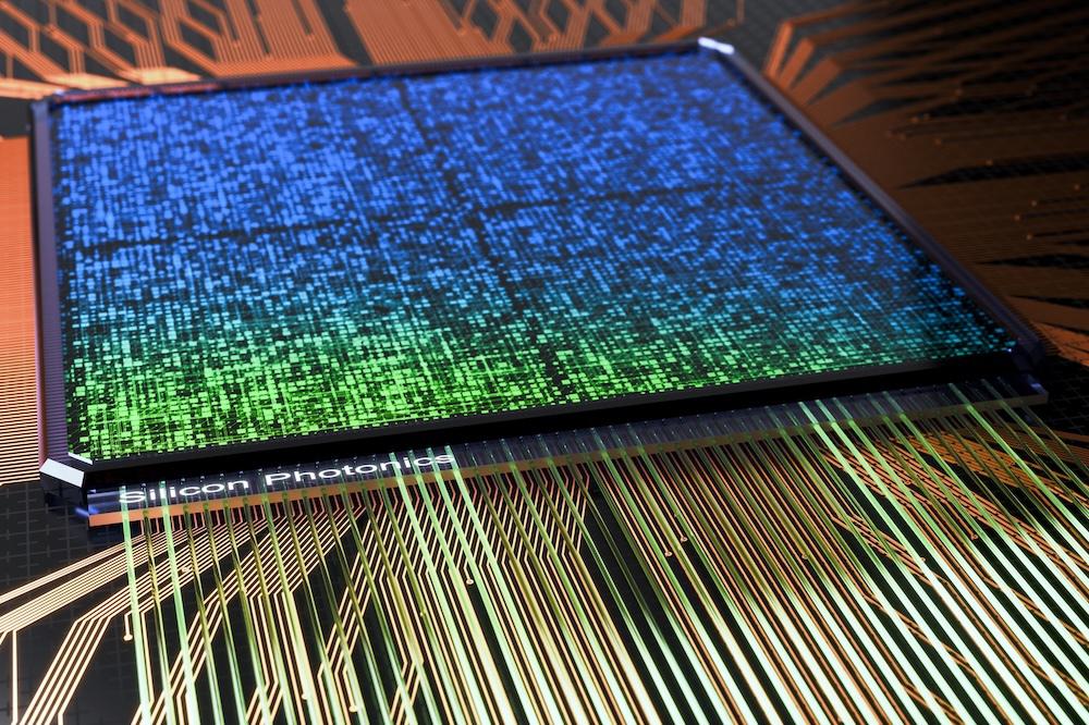
● Limited Applicability for Short Light Paths: OTDR is unsuitable for devices with extremely short light paths, such as photonic components or silicon photonics devices, where light travels over micrometers to centimeters.
When to Use Specific Testing Techniques
Choosing the appropriate method for insertion loss testing depends on system requirements and testing goals:
● Use direct testing for:
○ Routine fiber insertion loss testing in short- and medium-length fibers.
○ Verifying overall link integrity during installation and maintenance.
● Use OTDR testing for:
○ Troubleshooting long-distance fiber optic networks.
○ Diagnosing specific problems like splice loss, bends, or breaks.
○ Evaluating complex optical systems where precise fault location is essential.
Combining direct testing with OTDR techniques offers the most comprehensive insertion loss testing approach, ensuring overall system performance and fault diagnostics are achieved.
Santec Solutions for Insertion Loss Testing
Insertion loss testing requires precision, reliability, and advanced tools to ensure signal integrity in fiber optic networks. Santec provides cutting-edge solutions designed to meet these needs through the Santec STS Series—a suite of high-performance optical testing systems. These systems are trusted across industries for their speed, accuracy, and ability to streamline testing processes in research, development, and production environments.
Santec Solutions for Insertion Loss Testing
The Santec Swept Test System (STS Series) is engineered to deliver fast, accurate, and versatile optical component testing, making it a robust solution for fiber insertion loss testing.
● Purpose: The STS Series is designed to measure insertion loss and other critical parameters in optical components, such as splitters, couplers, and WDM devices.
● Target Users:
○ Research and Development teams in photonics laboratories.
○ Manufacturing environments need rapid, reliable insertion loss testers.
○ Quality assurance teams validating optical components.
The STS Series stands out for its integration of advanced tunable lasers and high-speed power meters, offering unmatched precision and efficiency in fiber optic insertion loss testing.
Key Features of Santec Component Testing Systems
The STS Series incorporates features that address the diverse requirements of insertion loss testing, ensuring superior results across various applications:
High-Speed Testing:
● The STS Series uses rapid scanning technology, significantly reducing testing time while maintaining accuracy.
● It enables high-throughput measurements, which is ideal for production environments where efficiency is critical.
Wide Dynamic Range:
● A broad dynamic range ensures the system can measure both low-loss and high-loss optical components accurately.
● This capability is essential for testing components like optical splitters or dense wavelength division multiplexing (DWDM) devices.
Precision and Accuracy:
● The integration of tunable lasers and a power meter provides consistent, repeatable measurements.
● The system is optimized to minimize errors and deliver reliable results for fiber optic insertion loss testing.
Advanced Software Integration:
● The STS Series comes with intuitive software for automated testing, data analysis, and reporting.
● Users can easily configure test parameters and analyze results, simplifying the testing process.
Scalability and Flexibility:
● The STS Series supports various wavelengths, making it suitable for a wide range of optical components and testing requirements.
● It adapts to evolving industry needs, including emerging technologies in silicon photonics.
Applications and Use Cases
The Santec STS Series is utilized across diverse industries and applications where insertion loss testing is essential:
Telecommunications:
● The STS Series ensures high-performance fiber optic networks by testing components such as couplers, transceivers, splitters, and WDM systems.
● Accurate fiber insertion loss testing guarantees minimal signal degradation, supporting seamless data transmission.
Photonics Manufacturing:

● Manufacturers rely on the STS Series to perform rapid, precise insertion loss tests on optical devices during production.
● The system’s high-speed capability improves throughput and reduces production costs.
Research and Development:
● In R&D labs, the STS Series is used to test next-generation optical components, including silicon photonics devices and ring resonators.
● Its precision allows researchers to validate new technologies with confidence.
Data Centers:
● For data centers, maintaining efficient cabling infrastructure is vital. The STS Series enables thorough fiber optic insertion loss testing to ensure all connections meet industry standards.
Aerospace and Defense:

● Optical components in mission-critical systems require reliable testing to withstand extreme conditions.
● The STS Series provides accurate measurements that validate component performance and durability.
Best Practices in Insertion Loss Testing
It is important to follow best practices to achieve accurate and consistent results in insertion loss testing. These practices ensure reliable measurements, minimize errors, and maintain system performance.
Regular Calibration
Regular calibration of insertion loss testers and associated equipment is essential to ensure measurement accuracy. Calibration compensates for equipment drift, environmental changes, and wear over time. Follow manufacturer guidelines and industry standards for calibration schedules to keep equipment operating optimally.
Using Appropriate Reference Methods for Consistency
Consistency in fiber insertion loss testing depends on standardized reference methods, such as the 1-jumper or 2-jumper methods. Proper referencing ensures accurate baseline measurements by accounting for connector losses and equipment variations. This practice is critical for reliable, repeatable results.
Documenting and Comparing Test Results for Validation
Thorough documentation of insertion loss test results is essential for validating system performance and ensuring repeatability. Along with recording measurements, it is important to document the measurement conditions, including wavelength span, scanning speed, step size, and output power.
Keeping track of these parameters helps identify trends, diagnose emerging issues, and ensure that components meet performance standards. Consistent reporting supports quality assurance and ensures compliance with industry benchmarks.
Conclusion
Accurate insertion loss testing is essential for maintaining the performance and reliability of fiber optic systems. The Santec STS Series offers a reliable, high-precision solution for fiber insertion loss testing, making it ideal for research, manufacturing, and quality assurance. Contact us for more information or to explore how Santec can support your testing needs.