
Optical alignment plays a crucial role in the assembly process of fiber optic components. This involves actively monitoring optical power while making mechanical adjustments. The desired outcome may vary, whether to minimize or maximize power. For devices that require high isolation, multiple signals need to be optimized at the same time. The difficulty increases when aligning a large number of channels or ports simultaneously. The optical power meter plays a vital role in this process by determining the efficiency and simplicity of the alignment procedure. The OPM-200 is well-suited for a wide range of optical alignment applications due to its multiple detectors, fast analog output response, high-speed power sampling, and simple SCPI commands.
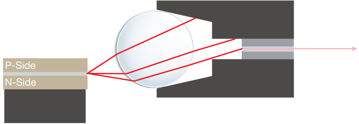
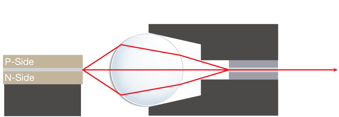
The OPM-200 can accommodate the full telecom wavelength range of 840- 1700nm. For standard single-mode and multimode applications, a 2mm detector is suitable. However, when dealing with free space alignment or larger core fibers, a larger detector may be needed.
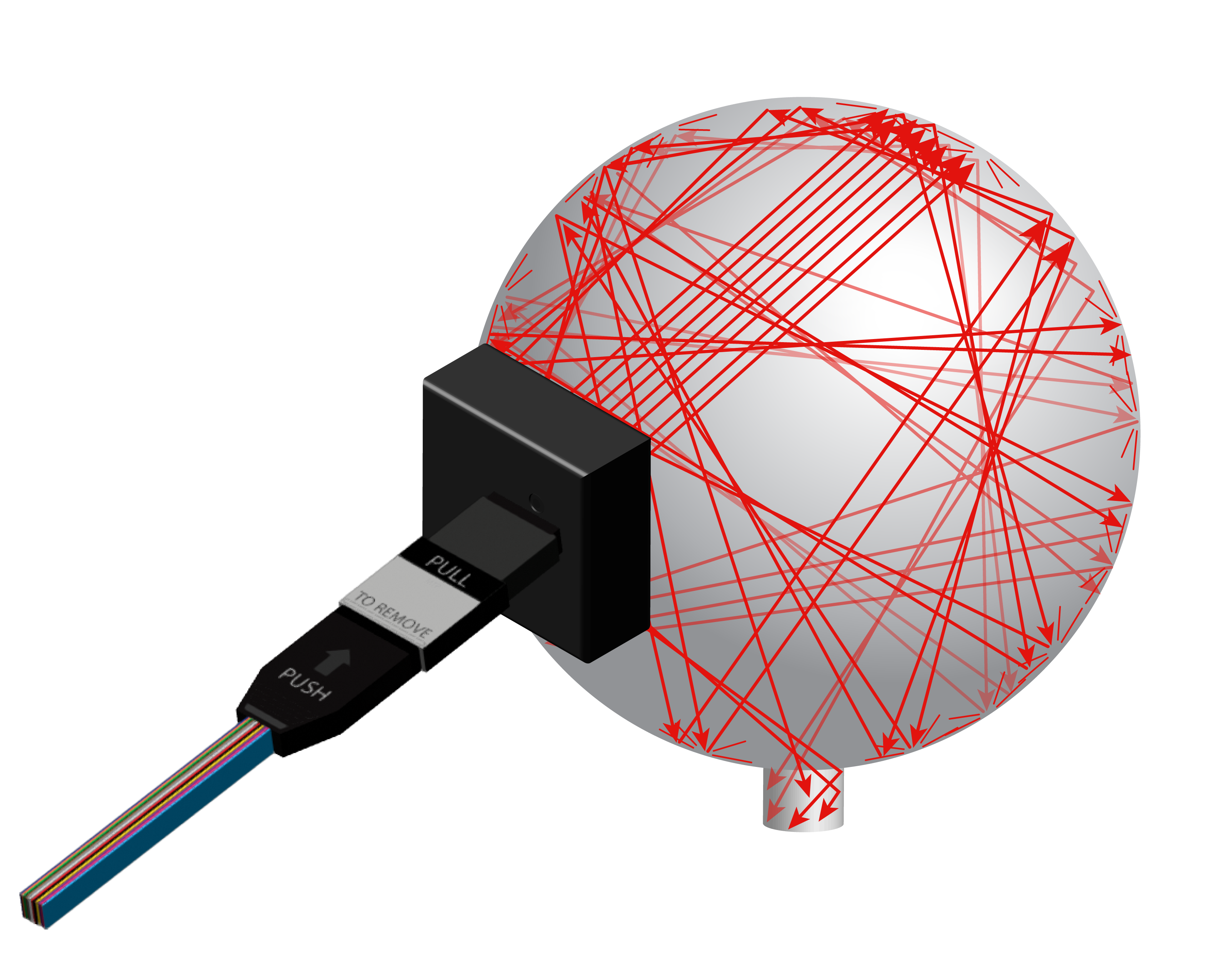
The OPM-200 offers the flexibility of an integrating sphere with an 11mm aperture, compatible with most larger beam sizes and providing a uniform response across the entire aperture ensuring accurate power measurements.
When developing the alignment process, it is common to start with manual alignment and then progress to automation. Therefore, selecting an optical power meter capable of functioning in both applications is crucial. Having a responsive front panel display and USB/Ethernet programmable functions, the OPM- 200 provides a pathway from manual to automated alignment.
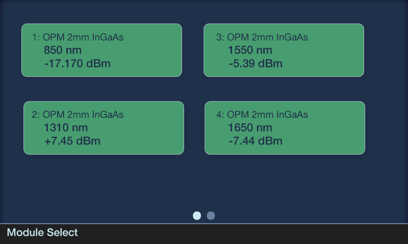
Many optical power meters lack displays and require a computer and coding to get started. The OPM-200 addresses this issue by allowing the display of up to four channels simultaneously, enabling immediate implementation without writing any code. When aligning a fiber array to a multiport device, monitoring multiple channels becomes necessary. Being able to view all channels at once allows one to see the effects of mechanical adjustment on all applicable ports effectively reducing the time to bring all ports into alignment.
In multifiber cases, the alignment process is not as straightforward as maximizing the level of a single port. Often, it involves balancing power levels on specific ports above a threshold. A typical process for a single row fiber array is to align only the outer fibers to meet the desired critera. In this case, it is assumed that the middle fibers’ alignment is sufficient if the outer fibers meet the criteria. These middle fibers may subsequently be tested and verified outside of the alignment process and failures can be found. With the OPM-200, the process can be further improved. By assigning two channels to outer fibers and two channels to inner fibers, the monitoring solution gives a more complete picture therefore increasing yield of the final product.

When monitoring power through the front panel, the display’s responsiveness is critical. The power response should be nearly instantaneous as adjustments are made during alignment. This real-time feedback indicates whether the system is becoming more or less aligned. The OPM-200 boasts a multichannel refresh rate of approximately 24fps for all channels, which exceeds the manual reaction time of a human.
Once the manual alignment process has been refined, it is advantageous to use the same optical power meter for automated alignment. There are two routes to automation in optical alignment. One involves utilizing the analog output (discussed later), while the other method involves writing a simple program to read power from the instrument and allowing a computer to control the entire process.
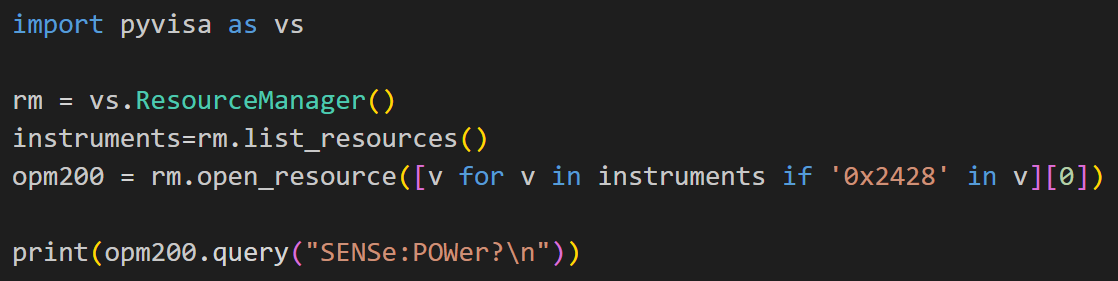
For integration with a computer, the OPM-200 utilizes simple SCPI commands via USB or Ethernet, a port available on all computers. The VISA driver is compatible not only with standard Windows OS but also with Linux and macOS, making integration into most manufacturing platforms easy. With just a few lines of code, power can be read from the OPM-200. SCPI commands can also be integrated into most measurement execution systems (MES), providing an additional degree of integration and automation.
The faster the software can read power from the instrument, the quicker it can communicate with the movement mechanisms to adjust and optimize alignment. Many high-speed optical power meters do not support fast on-demand measurements but instead provide measurements in batches or hold them in a buffer. The OPM-200 can deliver measurements to the computer on-demand in < 5ms.
Even faster feedback control can be achieved in the analog domain. The OPM-200 provides a proportional analog output response from 0 to 2.2 V that can be monitored. With a bandwidth of up to 10 kHz, it is suitable for even the fastest automated alignment processes.
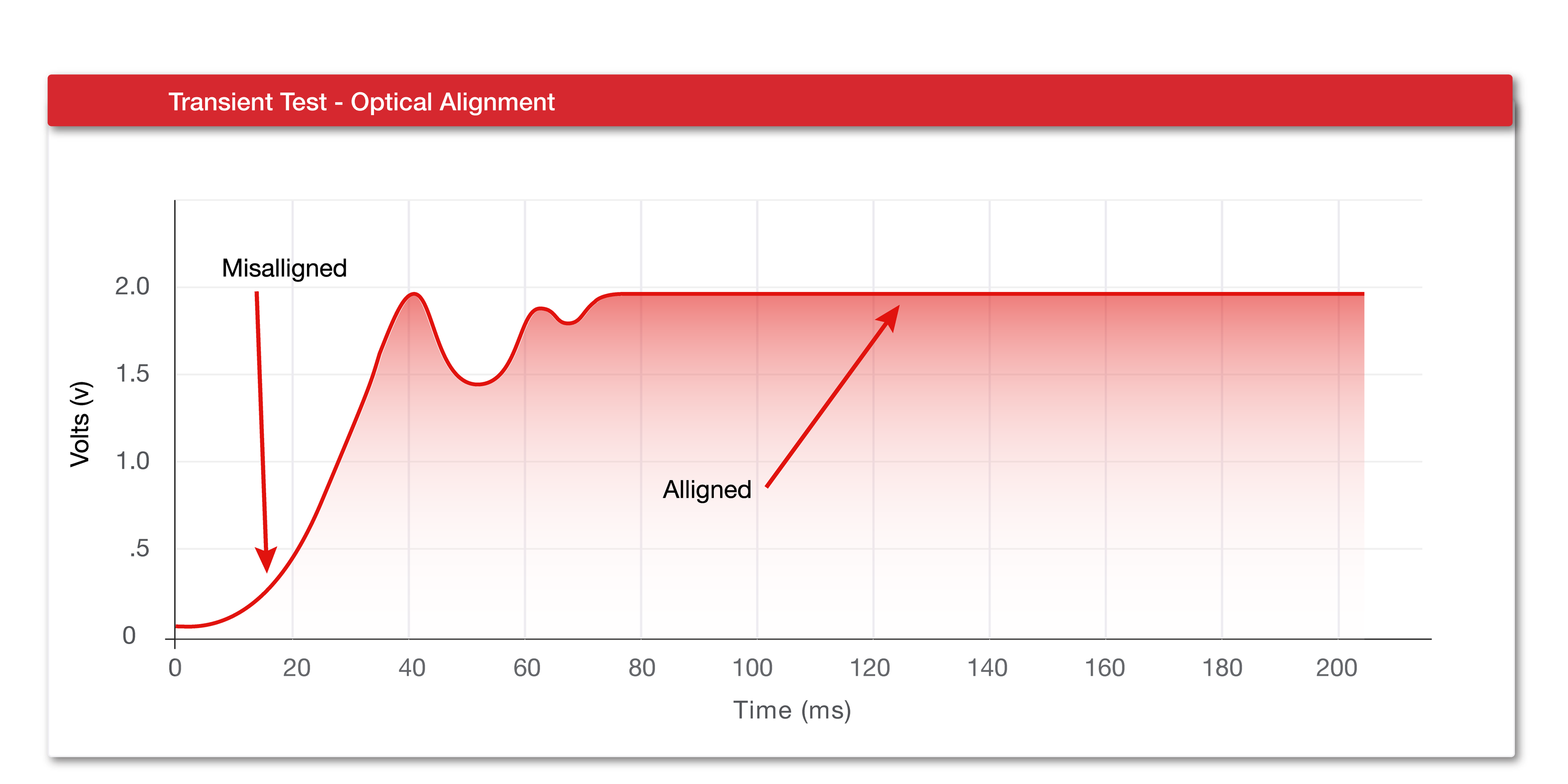
In some cases the initial alignment is significantly misaligned, making it impossible to detect any light. The alignment algorithm needs to step through multiple positions to find the “initial light”. A less sensitive power meter requires more iterations to find a minimum power level for detection. The OPM-200 has a sensitivity of -80 dBm allowing it to detect the smallest amount of light, reducing the time to detect the initial light and improving the throughput of the entire manufacturing process.
An optical power meter’s wide bandwidth at low power levels enables the movement system to rapidly iterate through positions to detect initial light. A lower bandwidth system would hinder the power level response of the OPM, resulting in slower light detection. If the movement system is moving fast, the optical power meter may not respond fast enough for the system to detect initial light, resulting in the system needing to iterate further or slower to find initial light. Many lower cost optical power meters have a bandwidth in the Hz range (1-10 Hz) for detecting power at the lowest levels. This allows for stable measurements with the increased averaging but leads to an extremely slow response time. In contrast, the OPM-200 offers a bandwidth of 1kHz at the -70dBm power level, allowing for the detection of abrupt power changes and easy detection of initial light, further improving the total speed of alignment.
The OPM-200 is an ideal optical power meter for alignment purposes, striking a balance between cost-effectiveness, high performance, and ease of use. Its front panel display and automation controls make it easy to transition from process development to process deployment in a manufacturing environment. The combination of wide bandwidth, high-speed on-demand acquisition, and deep dynamic range enables quick detection of initial light and effectively improves the overall throughput in the manufacturing process.
For more information on the OPM-200 and its capabilities, OPM-200 Product Page.